

 Roll Former
For the Uniform Coil Strand Group
by Elaborate Machine Group Harmony
Coil Feeding Section
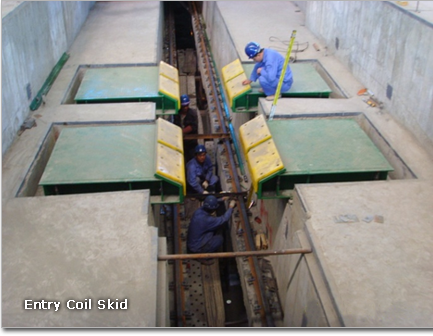
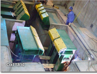
Entry Coil Skid
To avoid the line stopping when the overhead crane could not supply the coil on time, the coils to be slit are able to be laid on the saddles of this coil skids before they are moved to pay off reel by coil car. Coil skids are made of welded steel and mounted on the factory floor.
- Type : V-shaped saddle type
- Coils under 800mm diameter should be stocked directly on the coil car.
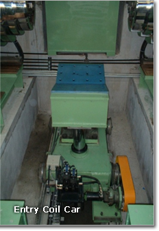
Entry Coil Car
Coil car is used to transport from coil skid to pay off reel and insert the coil into the drum in uncoiler.
- Type : Four wheeled car with V-shaped cradle type
- Lubrication : Central grease feeding system with hand grease gun. The grease gun will be mounted near of Floor level
Uncoiling Section
Uncoiler
- Shaft and bearing
- The mandrel shaft shall be made of forged alloy steel supported in lubricated roller bearings, and also acts as a output shaft of main housing.
- Mandrel
- Uncoiler has a wedge type expanding cone to grip the inside diameter of the coil. Mandrel expansion will be done by means of a hydraulic cylinder with rotary joint operating a pull rod in the shaft. The segments shall be made of cast steel coated with hard chromium.
- Mandrel drive
- Mandrel drive and free tension is controlled by AC vector motor through a gear box. Electromagnetic brake is provided to stop the line operation and for the emergency stop.
- Snub roll
- The snub roll will assist in feeding the strip to the pinch roll via threading table. The snub roll will be raised and lowered by hydraulic cylinder.
- Snub roll : 300mm dia. x 600mmL / Urethane rubber lined / Swing: By hydraulic cylinder / Swing: By AC geared motor
- Bearing supporter : Link type
- Up/down : By hydraulic cylinder
End supporter : Link mechanism type / Arm swing = Hydraulic cylinder
Front Slitting Section
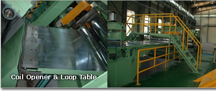
Coil Opener, Loop Table & Pinch Roller #1
Coil opener opens the head of coil and guides it into the pinch roll, and upward unwinding is available. After the strip is inserted into the pinch roll, the opener blade is retracted and the table is lowered away from the strip. The coil opener will be supported in bronze bushings mounted to the No.1pinch roll frame. The opener blade will be mounted on the tip of the threading table.
- Type : Telescopic and swing type / Hydraulic cylinder up & down / roll pinching
Entry Crop Shear with Scrap Box
This entry shear will be used for cropping the head of the coil. Shear unit will consist of the moving top blade and the fixed bottom blade. Safety spindle locking pin will be provided for each shear knife to prevent the knife moving by accident when the line is abnormal operation or stopped for maintenance.
- Type : Down-cut shear
- Shear knife : Four(4) cutting edges, Special alloy tool steel (SKD 11 or equivalent alloy tool steel)
- Knife fixing - by bolt screw with cross head
- Knife gap adjust method ; Adjusted gap of the knife by the taper slide installed between frame and knife
- Cutting capacity : Thickness 0.3 ~ 7.0 mm (Off-gauge : 150%) / Width : Max. 1,500 mm
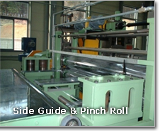
Side Guide
Side guide is located between entry shear and slitter. Side guide will be used to guide the strip and to adjust the center of line by AC geared motor. Side guide rolls will be measuring adjusted to center line controlled semi-automatic control system. The basic data of the product (plate width, thickness and any information) for adjusting of center line measuring received from PLC system.
The adjusted center line measuring method can doing controlled semi-automatic system with manual control system.
- Side guide open/close : AC geared motor with brake
- Quick open : Pneumatic cylinder Ø63mm x 75mm stroke
- Drive Power : By AC geared motor 1 set
Slitting Section
SLITTER Body & DRIVE UNIT
lit the incoming strip to the required width of multi-strands. Tooling makes the set up of tooling accurate and easier.
- Type : Normal arbor stand
- Cutter Head : 2 sets (1 set for in line and 1 set for changing)
- Working range : 0.3mmT ~ 7.0mmT
- Trimming / (Min. slitting) width : 900 – 1,500mm / (30mm)
- Main drive : AC vector motor with brake (55Kw)
SLITTER Head
The slitter head slits the incoming strip into narrow strands. The slitting head with arbors hardened, grind and polished, running in dust sealed anti-friction cylindrical roller bearings. Simultaneous motorized arbor height adjustment will be done by push button with indication for as well as manual adjustment by means of handle and screw. The arbor rotates by AC vector motor through intermediate gear box and clutch. Lubrication of gear train is done by oil bath. Other parts are lubricated by manual grease gun.
TOOLING (Ø350) Rotary Slitter Knives
Made of special alloy steel equivalent to JIS SKD 11 heat treated with vacuum heat treatment operation and precise grinding.
TOOL CHANGING CAR
- Type : Hydraulic operation, Shifting type
- Table : Welded steel shape construction
- Rails for two(2) stands set on the top Shifting traverse By hydraulic cylinder
- Electric supply : Cableveyor system
- Lubrication : Manual grease gun
Post Slitting Section
Run-out Conveyor
- Type / Roller width : Free roll conveyor type / 1,700mmW x 1 row
- Guide swing : By pneumatic cylinder
- Conveyor drive : By inverter controlled AC geared motor with brake through gear & chain
- Conveyor speed : Approx. 100m/min (Max.)
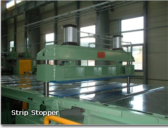
Strip Stopper
Grips the tail end of the strips when it passes out of the slitter head to prevent the strips end falling into the looping pit.
Apron guide provides the guide way for the strips at the exit of looping pit.
| Parts | Specification |
|---|---|
| End pad Type | Direct felt press |
| Pad surface | Covered by felt |
| Pad hold down | By pneumatic cylinder, Ø140mm Bore x 100mm Stroke |
| Apron guide | R type roll conveyor |
| Conveyor roll up/down | By hydraulic cylinder |
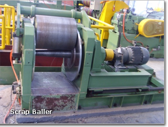
Scrap Baller
These equipments will be provided to wind both side of scrap after slitting. The wound scrap will be retracted by hydraulic cylinder of baller kicker.
| Item | Specification |
|---|---|
| Slit-scrap width | Max. 20 mm per each side |
| Ball size | 700 mm dia x 800mm length |
| Available ball weight | 200 – 300kg/ball |
| Winding shaft | The trimmed strip is clamped between the top and of the shaft and rotary plate. The shaft is retracted by a hydraulic cylinder to drop the balled strip. |
| Rider roll | Air cylinder operated rider roll is provided to press the trimmed strip at winding. Ø680mm x 790mm |
| Drive | The winding shaft is driven by VVVF motor(15Kw) |
| Winding speed | Max. 62 m/min |
Pre Recoiling Section
Loop Table
Threading table supports and guides the strips to go its right direction. End pad is operated by pneumatic
- Type : Hydraulic cylinder up/down
| Shaft | Shaft slide-out type / High carbon steel (S45C), Ø 140mm dia. x 1,700mmL, 1 set |
|---|---|
| Roll Keeping & Lifting |
By hydraulic cylinder, 2 pcs, Ø 63mm Bore x 70mm Stroke |
| Roll / Main frame | Steel tube, Urethane coated / Welded steel construction |
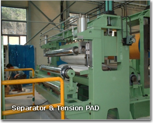
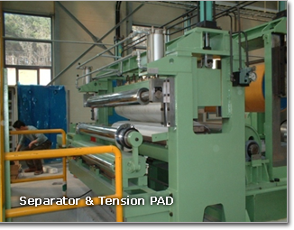
Separator
The separator will be provided in front of tension pad to guide every strand to their right positions which come up from looping pit. Keeping roll makes the strands kept in the right positions between spacers.
- cylinder to clamp the strip between two clamping pads which is covered by tear resistant felts.
Separator Discs
special steel, hardened and ground (JIS SUJ2 or SK5)
Tension PAD
It is designed to give the strands uniform tension for tight rewinding on recoiler.
Hydraulic cylinder provides clamping force on mating felt covered on hardwood pads. Felt of special tear resistant type is covered on wooden pads.
The clamping force between pads is adjusted by regulating the pressure of hydraulic cylinder.
| Type | Direct felt press type |
|---|---|
| Length of pad surface | 1,700mm |
| Upper pad lifting up/down | hydraulic cylinder, Ø125mm x 200mm Stroke - 2 pcs |
| No. of upper pad parting | 6 parts (manual screw adjustable) |
| Material of pad | Special felt or wood |
| Main frame | Welded steel construction |
| Lubrication | By manual grease gun |
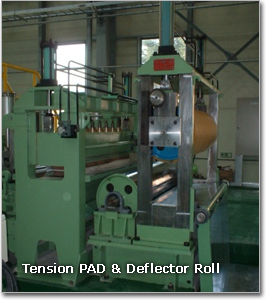
Deflection Roll
This unit can be fed the strip to recoiler after divide cut.
| Type | Vertical roll open/close type |
|---|---|
| Dimension | Ø200mm x 1,700mmL x 2 pcs |
| Materials | Alloy steel with PU Coated |
| Surface Treatment | by Hardening & Grinding |
| Upper roll Up/down | By pneumatic cylinder, Ø160mm x 150mm Stroke |
| Drive | by AC geared motor |
| Lower roll | Free roll with Static position |
Recoiling Section
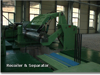
Recoiler & Separator
Provides tension to the slit strands and rewinds strands on the recoiler drum.
- Strip uncoiling can be done upward.
- Main housing is composed of gear reducer box, main drive AC vector motor, mandrel drum and hold down roll.
- It is made of welded steel construction incorporating all necessary reinforced ribs and is stress relieved and machined accurately.
- The recoiler drum shall be of the concentrically expanding and contracting type, composed of four steel segments mounted on a central main shaft and operated by four pair of companion wedges.
- The main shaft is alloy steel, runs in grease lubricated anti-friction bearings and enclosed in the gear box.
- At the rear end of the shaft, hydraulic cylinder connected with rotary joint is mounted to accomplish expansion and contraction of the mandrel drum by actuating drum wedges by pull rod through the inner bore of the shaft.
- The helical gearing is enclosed in the housing of recoiler.
- All gears are hardened & ground.
- A gripper will be incorporated in one of the segments fitted with two gripping element with the expanding and contracting of the drum.
Separator #2 / Coil Pusher
Keeps the strands on their right position and to be wound on the recoiler drum correctly.
- Separator positions each slit strand on the separator shaft uniformly as it begins to be wound on the recoiler drum.
- Exact alignment between the separator of loop exit and separator of recoiler makes the slit strips to be kept in their right position so that the strips can be wound on the mandrel drum of recoiler correctly throughout the entire coil build up.
- Pusher is mounted on the top of recoiler housing for stripping the slit coils off from the recoiler drum.
- The pusher consists of fabricated steel plate supported by guide rod which slides in bronze bushings.
- The pusher is moved forward and backward by a hydraulic cylinder.
Bearing Supporter
Prevents the deflection of the mandrel shaft of recoiler and reduces the Load on the main bearing of recoiler mandrel shaft.
- The supporting roll placed on the top of reciprocating sleeve actuated By hydraulic cylinder is provided underground pit for supporting the Outboard bearing of recoiler main shaft to prevent bending.
EXIT COIL CAR
Is provided to take the coil from the Rncoiler to Coil skids and Two arm unloader, It travels on the rails fixed under ground pit.
- Lift frame is heavy-duty welded construction, and consists of V-shaped saddle with replaceable synthetic resin (MC-nylon or urethane), hydraulic cylinder, and retract guide bars.
- Lift frame will be movable upward and downward by hydraulic cylinder, and guide by retractable guide bars.
- Carriage is made of welded steel construction and equipped with four (4) wheels mounted in anti-friction bearings.
- Traverse will be done by AC 7.7kw cyclo drive motor.
- Cableveyor for leading electric wires and hydraulic hoses to the carriage will be provided.
Recoiling Section

EXIT COIL SKID
In order to avoid the line stopping when the overhead crane could not supply the coil on time, the coils to be slit, are able to be laid on the saddles of this coil skids before they are moved to pay off reel by coil car. Coil skids are made of welded steel and mounted on the factory floor.
WEIGHER
The product will be weighed on exit coil skid by 4 sets of load cell and the controller.
| Measuring capacity | Max. 15,000 kg |
|---|---|
| Frame | Welded mild steel manufactured |
| Load cell | Four (4) |
| Scale range | 1,000 ~ 15,000kg |
| Increment | 5kg |
| Accuracy | ±5kg |
STRAP BANDING TOOL
To make strap bending the circumference of coil by manual.
| Type | Manual Type |
|---|---|
| Quantity | Air operated with weight balancer - Two(2) sets |
| Band | 0.8mmT x 25mmW |
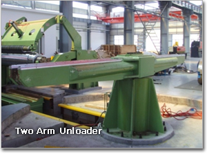
TWO ARM UNLOADER
Two arms is rotated and stopped on changing position so that the exit coil car can lift up the slit coils and to put the slit coils into arms of unloader.
| Type | Two(2)-arm turning type |
|---|---|
| Capacity | 15ton x 2coils |
| Rotation | Hydraulic motor rotates the two(2) arms mounted on slewing bearing. |
HYDRAULIC EQUIPMENTS
- Pump and Motor : Piston with AC motor, one set
- Normal working pressure : 100 kg/cm2
- Max. working pressure : 140 kg/cm2
- Piping works : Piping works in machinery and piping works unit and each equipment are included.
PNEUMATIC EQUIPMENTS
- Normal working pressure : 5 kg/cm2
- Max. working pressure : 7 kg/cm2